1.22. Person Smart Control
This component can be used to control the power states of Units in the appartment via pointing gestures and speech or get information on pointing gestures. Moreover, a GUI component to visualize the pointing control process is described in BCO Stage.
1.22.2. Introduction
The Person Smart Control component can be used to acquire information about gestures and speech interactions performed by a user, their intent and targets. It also allows the user to directly control the service states of units by for example pointing at them and saying “on”.
For this purpose, the component is divided into several submodules:
| Module name | Command | Description |
|---|---|---|
| Skeleton Merging | bco-psc-skeleton-merging |
Merges the tracking data from multiple devices into a single rsb event. |
| Ray Extractor | bco-psc-ray-extractor |
Extracts pointing rays and probabilities from tracked joint locations. |
| Identification | bco-psc-identification |
Identifies pointing targets and their probabilities. |
| Speech | bco-psc-speech |
Converts the Speech Hypotheses to action parameters. |
| Dummy Intent | bco-psc-dummyintent |
Allows to send dummy intents to control Control. |
| Control | bco-psc-control |
Controls the service states of objects identified by Identification. |
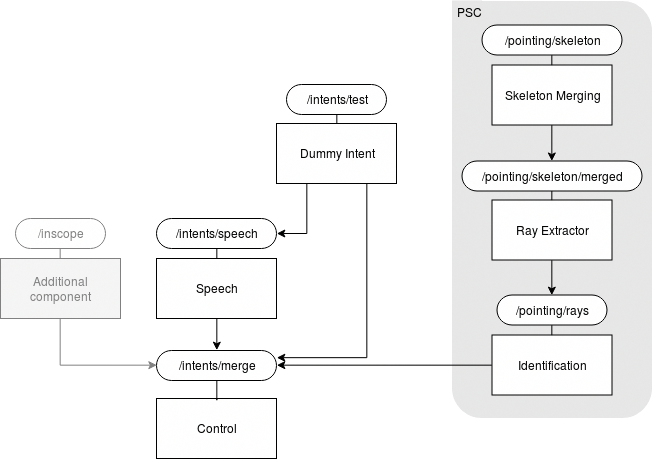
The PSC box in the figure above refers to the old Pointing Smart Control. Pointing Smart Control consits of the modules Identification, Ray Extractor and Skeleton Merging. The Person Smart Control (PSC) component was formerly known as Pointing Smart Control. The names was changed to better reflect the possibility of using multiple modalities. This was introduced by the change of Control and addition of the Speech module.
It is also possible to start all modules using the call bco-psc or exclude single modules by adding --print-launcher or --exclude-launcher to the call. Adding -h to any of the commands will give an overview of available parameters and their meaning. A more detailed list can be found in the Modules description below.
To validate the results of the modules as well as object locations inside the apartment, the BCO Stage and Speech component can be used.
1.22.3. Requirements
In order to use Person Smart Control, the BaseCubeOne component needs to be running. Tracking devices (e.g. the Kinect 2) have to be set up and registered to the bco-registry in order to receive the required postures streams for Skeleton Merging. The procedure to setup a Kinect to be used by Pointing Smart Control is described in section Setting up a Kinect node. Furthermore, you will need to register object locations and set up unit groups for objects that should be controlled by the Control component (see section Registering object locations).
1.22.4. Modules
There are several parameters that are used across multiple components or even in all of them:
| Parameter | Description |
|---|---|
--scope-base-psc |
This is the base scope on which all psc components communicate. |
--scope-for-merged-postures |
The subscope underneath the base scope on which merged postures created by skeleton-merging are sent. |
--scope-for-rays |
The subscope underneath the base scope on which rays created by ray-extractor are sent. |
--scope-for-units |
The subscope underneath the base scope on which selected units selected by by identification are sent. |
--psc-unit-filter |
List of possible Meta-config entries that qualify a unit for the use in psc. |
1.22.4.1. Skeleton Merging
The Skeleton Merging component is responsible for transforming the tracked postures delivered by a Kinect (or other input source) into the root coordinate system and merge the inputs of multiple sources into a single output at a constant frame rate. Usually the component will check the BaseCubeOne registry for applicable input sources and derive their transformations and scopes from there. Therefore, you have to make sure to register all input sources appropriately (See Setting up a Kinect node). Moreover, it can provide a linear stabilization for noisy inputs. This component can be configured using the following additional parameters:
--scope-base-raw-posturesdefines the scope on which the listener is initialized. Keep in mind that the scopes of the inputs should be subscopes of this scope. The inputs will be filtered by type also.--sm-frame-ratein Hz at which output is generated. The default value 30 Hz is the average frame rate of Kinect 2s.--sm-stabilization-factoris the percentage of the new frame that will be made up by the previous frame (for postures that occur for both). The rest is the merged result of each input source’s last frame. If the stabilization-factor is very high a delay will be noticable in the movements of the tracked postures (for 1.0 there will be no changes after the first frame) which is a side effect of the smoothing.--sm-registry-transformerscan be specified to restrict the input sources to a specific set. The parameter has to be provided with a list of unit ids that belong to input sources registered in the BaseCubeOne registry. If it is not specified, all suitable devices configs of the device classes specified in the next parameter will be considered as input sources.--sm-device-classesis a list of unit ids of device classes whose instances can be used as input sources. The default value is the id of the Kinect 2 class in the csra registry.--dr/--disable-registry. If this parameter is used, no input sources from the BaseCubeOne registry are used. This can be helpful for offline testing using transformation files.--sm-file-transformersis a list of scopes and transformation files which can be used for offline testing. Please refer to the code for the applicable file format. An input on the given scope will be transformed by the transformation specified in the file and then contributed to the merging process.
1.22.4.2. Ray Extractor
The Ray Extractor component extracts pointing ray distributions from the tracked postures merged in the Skeleton Merging component. These are sets of rays that belong to a single arm of a tracked posture. The sets can contain a single ray with the overall estimated pointing probability or multiple rays whose summed probability is the overall estimated pointing probability. To filter the ray distributions by a minimal overall probability, you can specify a parameter --re-threshold.
The ray extraction process occurs in two steps. First the probability of a pointing gesture is calculated for which several options exist which can be specified using the parameter --re-extractor:
SIMPLEdefaults to a probability of 1 times the certainty of the tracking of relevant joints and thus is unuseful for most applications.ARM_POSTUREworks based on joint angles for a single arm that are classified based on a study-generated corpus (see CEORAUP for more details). Simplyfied it can be said that the more the hand is on chest level and the more the arm is straight the higher the calculated probability becomes. This strategy can be used to achieve a fast response by the system, as the probability is calculated based on a single frame. However, this configuration can lead to false positives in case of unintended short pointing gestures.POSTURE_DURATIONAlso uses theARM_POSTUREstrategy to calculate the probability of a pointing gesture for a single arm. However the probability is reduced by a factor and increases over time to its original value, if this is above a certain threshold. It is probably the most useful strategy as it can be configured in a way that suits every need from a fast response to a high avoidance of false positives. The configuration can be done using the following parameters:
--re-duration-reduction-factordefines the factor by which the base probability is reduced initially. This factor will then be increased linearly to 1.0 over the lookback period.--re-duration-probability-thresholdis the threshold which has to be exceeded by the base probability to cause an increase of the reduction-factor. If the base probability falls below the threshold, the reduction-factor will be reset to its initial value.--re-duration-max-angledefines the maximal angle difference in the shoulder-hand vector that may occur during the lookback period. If the angle is exceeded this indicates that no pointing gesture exists because there is too much movement.--re-duration-lookbackis the period of time in milliseconds during over which the reduction factor is increased from its initial value to 1.0. If it reaches 1.0 it will remain at that value until the base probability drops below the probability-threshold or the arm is moved more than the max-angle inside a single lookback-period.Note
Setting the
--re-duration-reduction-factorto 1.0 makes the output equivalent to theARM_POSTUREstrategy
Multiple solutions have been implemented for this
1.22.4.3. Identification
The task of the Identification component is to determine what object pointing rays are directed at and with which probability a pointing gesture at a certain object occured. It receives collections of PointingRayDistributions and calculates UnitProbabilities based on these. Beside the default parameters, the following options are available:
--identification-distance-measuretakes one of the valuesANGLEandORTHOGONALand selects the corresponding distance measure. Angular distance is the default which has worked well so far.--identification-unit-selectortakes one of the valuesMAXandMEANand defines in what way the probability results of a pointing ray distribution are reduced to a single value (Mean value over the rays vs. max of the rays). In combination with the other components and settings, onlyMEANworks at the moment, which is the default value.--identification-thresholdis a probability threshold which can reduce the traffic for certain applications. If set to its default value 0.0, the probabilities for all relevant objects are sent via rsb on receiving pointing rays. Otherwise, the results are filtered using the threshold first.
1.22.4.4. Speech
The speech component is responsible for converting speech into actions that can change the status of units.
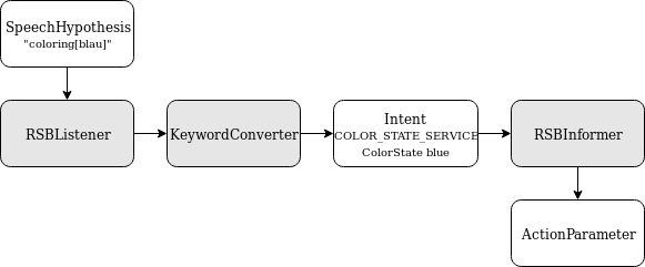
The component receives speech not as raw audio data but Speech Hypotheses objects, meaning its RSB connection “listens” for such events. Whenever a Speech Hypotheses event is detected, the component converts it to a corresponding ActionParameter.
The keyword converter class is used to convert Speech Hypotheses objects into their respective intent (if existing). An intent refers to a state service and its value, such as the color state service with value ‘blue’, or the power state service with value ‘off’. The necessary information is saved in the grammar tree with the syntax state_type[value] (e.g coloring[blau]).
Having extracted the intent from the grammar tree, it has to be matched to an ActionParameter. The mapping of intents to Action Parameters is created when the speech component is launched. It maps simple strings (grammar tree) to state service and value. Once an ActionParameter is built, it is published by via speech component’s RSB connection and sent to Control.
Entries can be added to the intent-action mapping by building value and service states, as seen below:
ColorStateType.ColorState blueState = ColorStateType.ColorState.newBuilder().setColor(blue).build();
builder = ActionDescriptionProcessor.generateDefaultActionParameter(blueState,        ServiceTemplateType.ServiceTemplate.ServiceType.COLOR_STATE_SERVICE);
builder.getActionInitiatorBuilder().setInitiatorType(ActionInitiatorType.ActionInitiator.InitiatorType.HUMAN);
mapping.put("coloring[blau]", builder.build());
1.22.4.5. Dummy Intent
This component allows to send dummy intents to Control and therefore to test the control component.
In order to do this you can send a string to the scope /intents/test.
unit will send the unit small ceiling lamp
The other input will be send in the grammar tree of the Speech Hypotheses object. See Speech for more details concerning the purpose of this.
Usage example for changing the color of the small ceiling lamp into blue:
rsb-toolscl send '"colorstate[color:blau] unit"'
1.22.4.6. Control
The Control component switches service states of a unit.
If the control module operates in the multimodal mode this is done by merging the different intents. This module seperates between two kinds of intents.
- The selection of a specific unit via UnityProbabilityCollections
- The selection of a specific action via ActionParameters
If it receives a UnitProbability with probability above a certain threshold on the selected-unit-scope and a matching ActionParameter it will perform the corresponding action.
If it operates in the non multimodal mode it will change the PowerState of the units when they are pointed at with a probability above the threshold.
The mode can be controlled with the flag --enable-multimodal-mode BOOL
The probability threshold can be set using the parameter --control-threshold.
However, the default value of the program should work best in most scenarios.
1.22.5. Setting up a Kinect node
1.22.5.1. Computer preparation
First of all you need to prepare a computer to be able to stream the Kinect data by following these steps (Don’t install the Kinect in the final location yet!):
- Install Windows 8 or 10 from an image or freshly.
- Kinect for Windows
- Install the Kinect Studio and SDK for Windows (https://www.microsoft.com/en-us/download/details.aspx?id=44561)
- Make sure that USB 3.0 is enabled (check the BIOS)
- Connect a Kinect
- Search the applications for SDK Browser 2.0 (Kinect for Windows) and run the Kinect v2 Configuration Verifier
- Open Kinect Studio, go to File -> Settings and check Automatically connect on startup
- Close Kinect Studio
- Network access
- Set a computer name
- Register the computer’s mac adress to receive the same IP adress every time in the local net
- Install VNCViewer
- Connect the computer to the local net (192.168.75.121 pug.locnet & 192.168.75.120 apw.locnet)
- Check whether you can access the computer using VNCViewer
- RSB publishing
- Copy the folder
Trackingof the repository https://github.com/csra/kinect-pose-rsb-setup toC:\and make sure, the folderC:\Tracking\Binary\is registered in the PATH environment variable- Copy the folder
C:\Tracking\config\to the user directory of the current user (This contains the rsb config file)- Create a link to the file
C:\Tracking\start_tracking.cmdon the Desktop and in the startup directory of the computer- Make sure bco is running and accessable via the DSC-computer
- Run the file and wait a few seconds
- Two windows should now be open: Kinect Studio and a console window with the following content:
Defined 1 streams!
1508861192884 rsb.depthsensors2.kinect2.kinect2device [WARN]: The Kinect2SDK only allows usage of one default sensor!
Waiting for termination signals is not implemented for this platform. The program will still terminate when such a signal is received but without shutting down properly.
If this is not the case:
- check network and rsb connection as well as the rsb.conf
- check the start_tracking.cmd file
- From another computer run an rsb logger on scope
/pointing/skeleton/COMPUTER_NAMEwhereCOMPUTER_NAMEis replaced by the name of the computer and verify that data is published- Test that the last two points also happen automatically after a restart of the computer.
1.22.5.2. Placement
After the computer is set up and you tested connecting to it using VNCViewer and confirmed the correct output of the posture stream, you need to create a new Kinect 2 device config in the BaseCubeOne registry.
- Note down the serial number of the Kinect
- Install computer and Kinect in the correct location (Also check the camera view using VNCViewer and Kinect Studio)
- Now place a marker on the ground in the camera’s field of view as described in Camera Calibration and take a screenshot using the program Color Basic - D2D of the SDK Browser 2.0 (Kinect for Windows).
- Mirror the image along the x axis (Kinect takes mirrored images)
- Follow the instructions in Camera Calibration to extract the camera location from the image also using the files: cameraPose.yml and markerSetConfig.yml from the repository https://github.com/csra/kinect-pose-rsb-setup.
- Copy the location to a file which should have the following type of content (otherwise convert it):
RVEC: [-0.95784086, -0.11953047, 0.26125339;
  -0.2638337, 0.725905, -0.63518012;
  -0.11372176, -0.67732888, -0.72683764]
TVEC: [0.3816631;
  7.7323795;
  2.9691384]
Note
Don’t forget to add the location of the marker to the TVEC if necessary!
- Run
bco-psc-create-kinect -n NAME -p FILE -s SERIAL -l LOCATIONwhereNAMEis the name of the computer set in 3.1),FILEis the file created in the previous step,``SERIAL`` is the Kinect’s serial number on any computer connected to the live systems spread ring andLOCATIONis the name of the location, that the Kinect should be placed in. - Check the results using the Registry Editor.
- To improve the location (but not rotation) of the Kinect in the BaseCubeOne context, use the BComfy component (very carefully, to be as precise as possible).
Note
To simply update the name/location data of a Kinect you can use bco-psc-update-kinect.
1.22.6. Registering object locations
To use the locations of objects in the registry, first add an entry (POINTING_GESTURE, true) under MetaConfig of the unit in the Registry Editor.
Make sure that the units bounding box is set either in the UnitConfig, its DeviceConfig or the DeviceClass.
You can then register the object location using the component BComfy.
1.22.7. BCO Stage
The Stage component was designed for the testing and visualization of the PSC processing steps inside the CSRA. Its functionality can also be used to verify locations entered in the BaseCubeOne registry. To only show pointing related objects defined in the Meta-Config of the Units, enable the filtering using the parameter -f/--filter-units. If no connection to the registry is available, the skeletons and rays can still be visualized using the --dr/--disable-registry flag. Other parameters are:
| Parameter | Description |
|---|---|
--scope-base-psc |
See Modules |
--scope-for-merged-postures |
See Modules |
--scope-for-rays |
See Modules |
--scope-for-units |
See Modules |
--psc-unit-filter |
See Modules |
-f/--filter-units |
Limits the visualization of objects to Units specified in the --psc-unit-filter parameter |
--dr/--disable-registry |
Disables the connection to the BCO registry. |
After starting up the program, the user has a number of controls to change the view point as well as displayed information. The controls are:
| Control | Function |
|---|---|
W/A/S/D |
Move the camera horizontally |
Ctrl/Space |
Move the camera down/up |
Mouse movement + LMB |
Turn the camera around |
1 |
Toggle displaying of Zones (as defined in https://openbase.github.io/bco/) |
2 |
Toggle displaying of Tiles (as defined in https://openbase.github.io/bco/) |
3 |
Toggle displaying of Regions (as defined in https://openbase.github.io/bco/) |
X |
Toggle displaying of the axes |
P |
Toggle displaying of the postures or skeletons |
R |
Toggle displaying of the pointing rays |
O |
Toggle displaying of the objects |
F |
Toggle displaying of the walls |
M |
Toggle displaying of the rooms (includes Zones, Regions and Tiles) |