1.19. Camera Calibration
This component computes the intrinsic parameters of cameras using a checkerboard. Furthermore it computes the cameras’ pose using the intrinsic parameters and a fiducial marker.
1.19.2. Interfaces
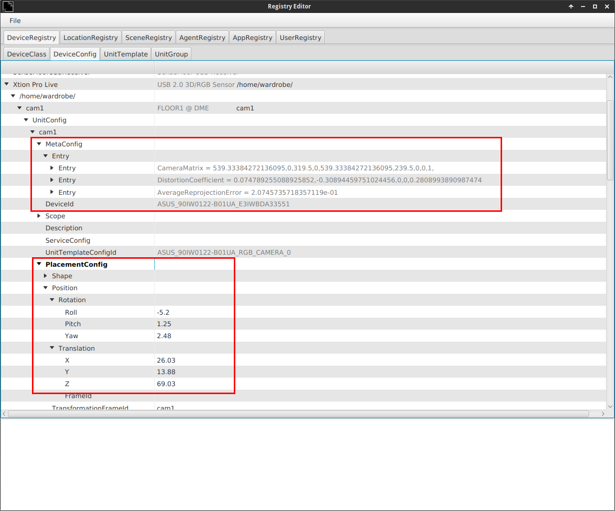
The Listeners recieve rgb images via rsb-scopes. See RGBD-Grabber for correct scope names. The calibration and camera pose estmation results are written to the device config of each specified camera in the registry.
1.19.3. How to calibrate
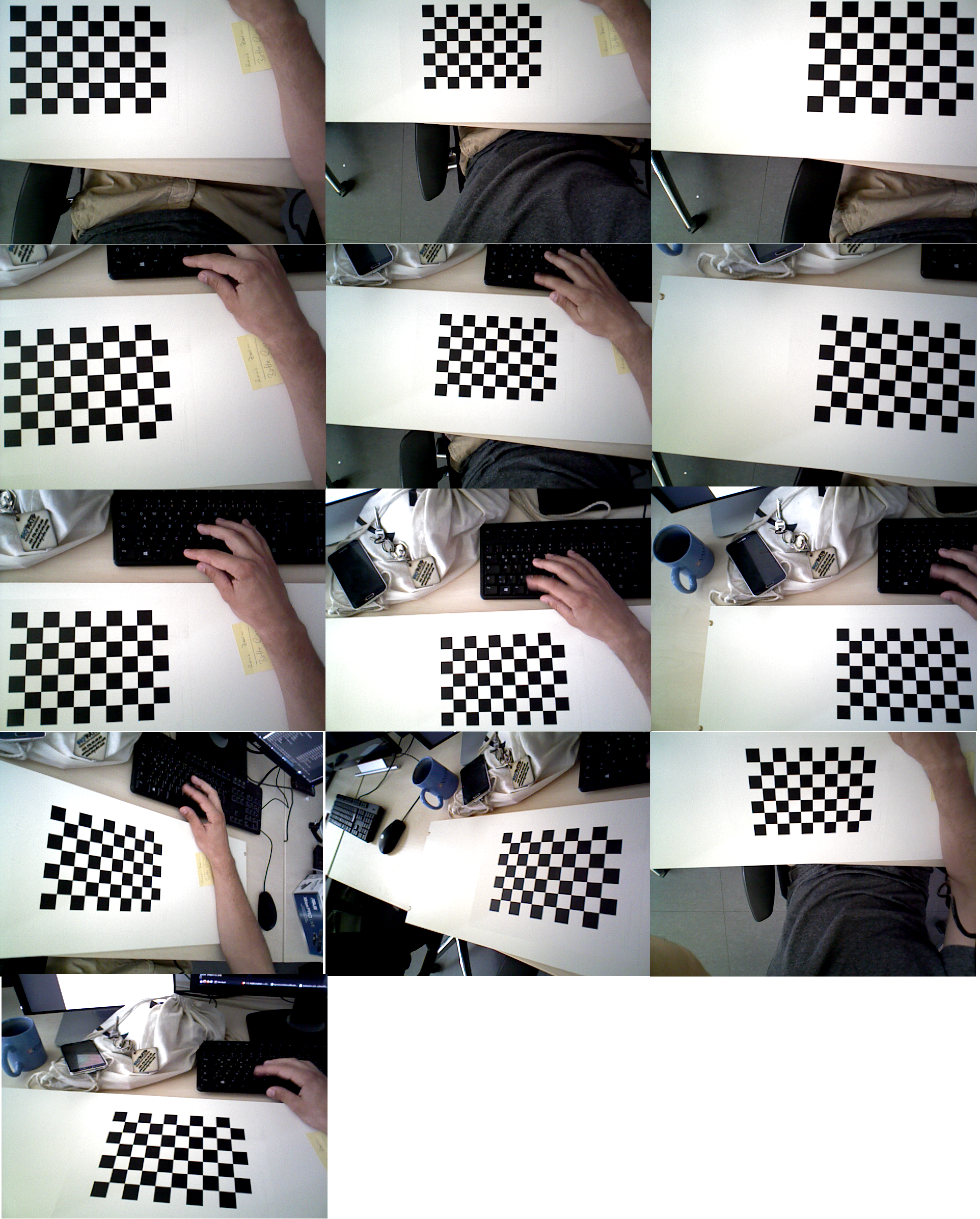
Take images in each corner of the FOV, in the middle of each of the edges and in the center of the FOV. Also try to take at least 2 images where the checkerboard is slightly angled. If this makes no sense to you, below is an example of images taken for a decent calibration.
A good calibration will produce a reprojection error between 0 and 0.2 (realistic values are between 0.13 and 0.2).
At the moment, the calibration is done per hand, this means you have to create the file images.xml in the
directory of the camera-calibration-calibration application, where you specify the path to the images.
The content of images.xml should look like this:
<?xml version="1.0" encoding="UTF-8"?>
<opencv_storage>
        <images>
                /path/to/image1.png
                /path/to/image2.png
                /you/get/the/idea.png
        </images>
</opencv_storage>
Use a program to capture lossless images from the camera (for example the image-saver inside this project).
Now run ./camera-calibration-calibration -d $UUID. You can view the UUIDs for each camera inside the registry-editor.
If you get a bad average reprojection error, run the calibration with -r false. This creates calibration-config.xml, where you can see the
reprojection errors for each individual image. Capture new images for images with big reprojection errors.
You can also (but this is optional) specify the size of the squares on the checkerboard in the etc/calibration-config.xml file.
If you use a checkerboard with a different number of rows and columns you should (and this is not optional) specifiy it there, too (Only the inner squares are used for calibration.
so if you use a 10x7 board, you actually have to write 9 rows and 6 columns).
1.19.4. How to compute the camera pose
Start the program via vdemo and place the marker in the specified location for the desired camera. If the marker position is stable for a certain amount of time, the camera pose will be written into the device-registry. The correct locations for the markers can be found here. This file also holds information about the marker size. If you want to use a different marker, you have to adjust the parameters there.
1.19.5. Examples
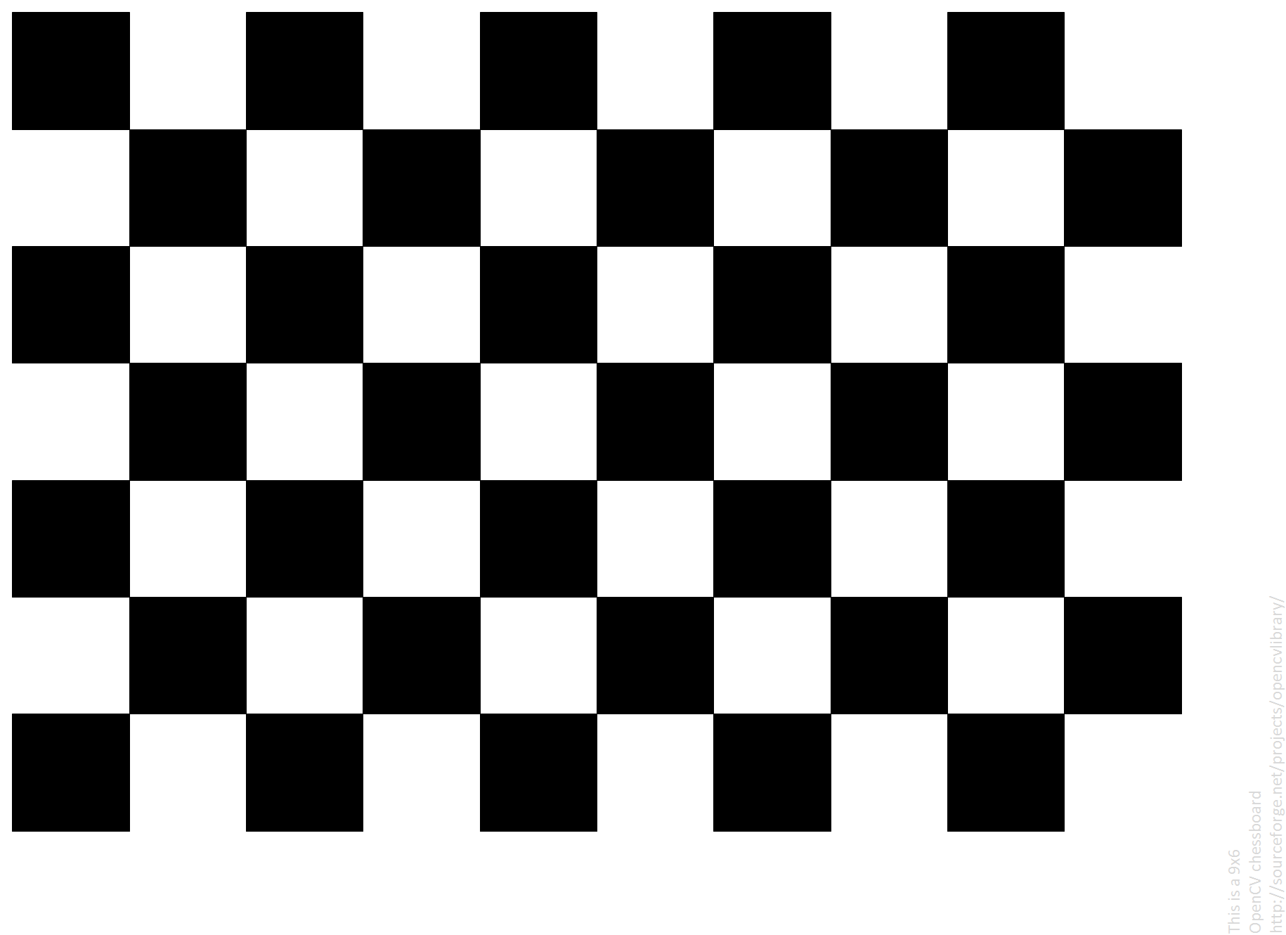
This is the checkerboard used for calibrating the cameras and calculating the intrinsics parameters.
This is a bch marker used for calculating the camera pose.

Todo
expand everything.